2019/02/19
Actuator
Ultra-compact dual encoder case
As robotics advance, Higher joint integration demands compact, highly integrated encoders that shape joint design and maintenance. Kingkong Technology’s unique patterned magnetic tech measures two axes in a tiny space—truly one of a kind worldwide.
While achieving an extremely compact dual-encoder design, it also delivers high-precision measurement, laying the physical foundation for integrated joints that enable robots across various industries.
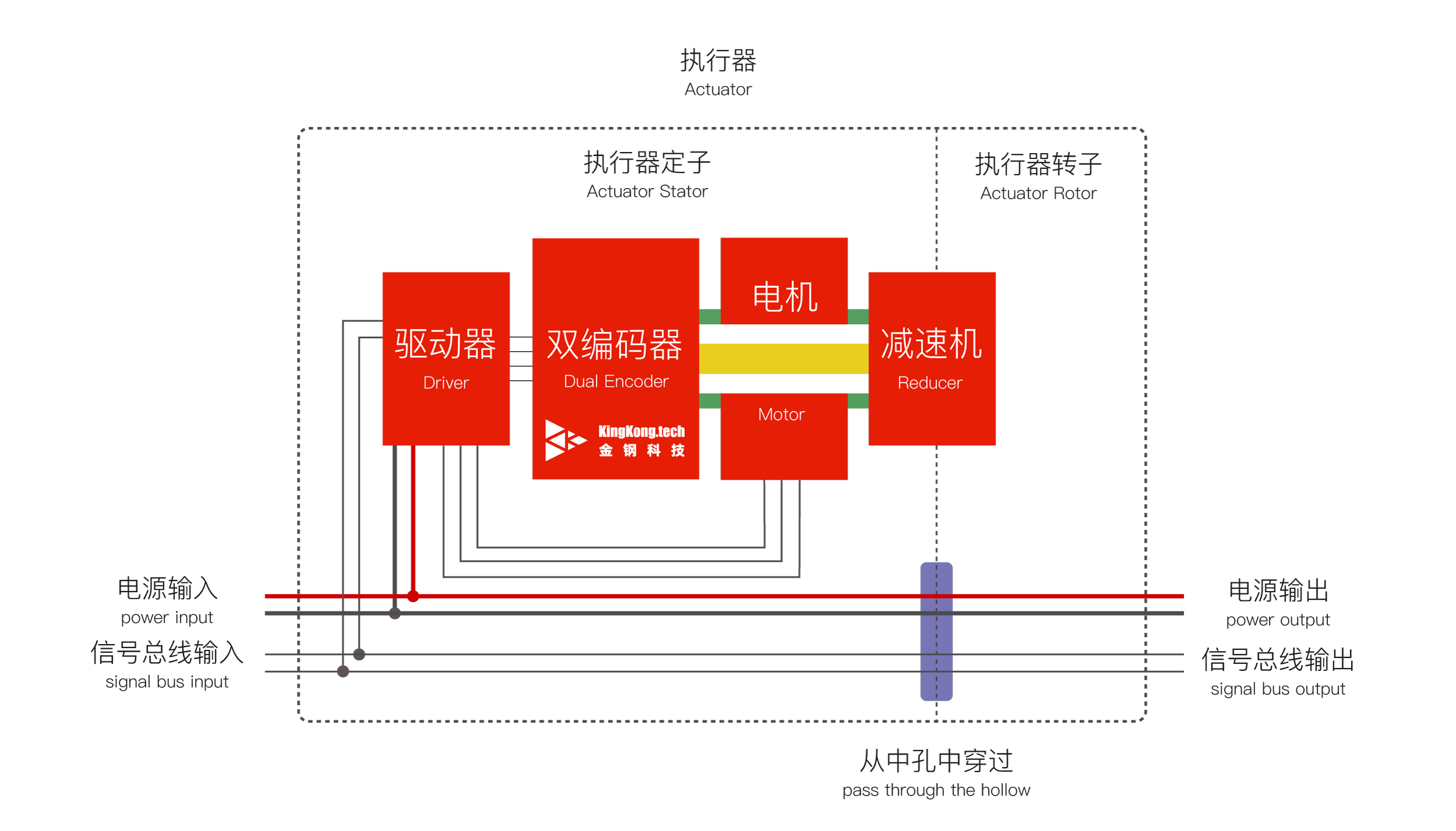
Joint demonstration
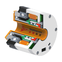
In this setup, Kingkong’s DPT dual encoder enables joint miniaturization with a nearly invisible footprint, allowing ring-shaped driver placement and greatly reducing joint length.
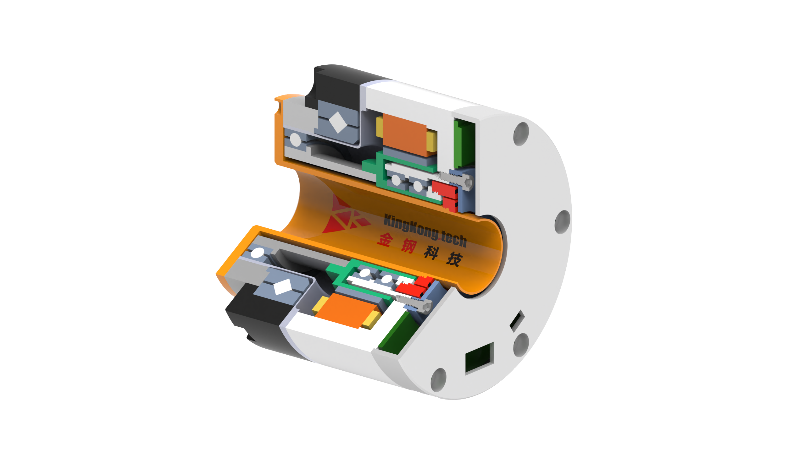
DPT Dual Encoder
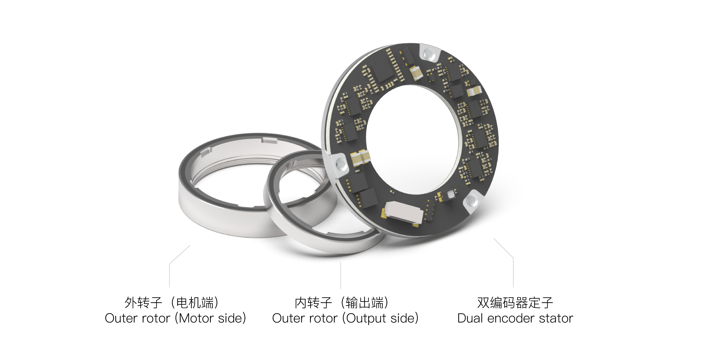
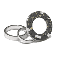
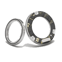
The DPT dual encoder consists of three parts:
- Outer rotor: Mounted on the motor side
- Inner rotor: Mounted on the output side of the gearbox
- Dual encoder stator: Simultaneously measures the angles of the inner rotor (motor side) and outer rotor (output side) and outputs them through a single interface.
This series employs KingKong Technology’s separate patterned measurement for inner and outer rotors, achieving high precision without mutual interference despite their close proximity
Ultra-compact integrated joint implementation
In this solution, KingKong Technology’s DPT series integrates dual encoders into an ultra-compact size, enabling higher integration and miniaturization of the integrated joint.
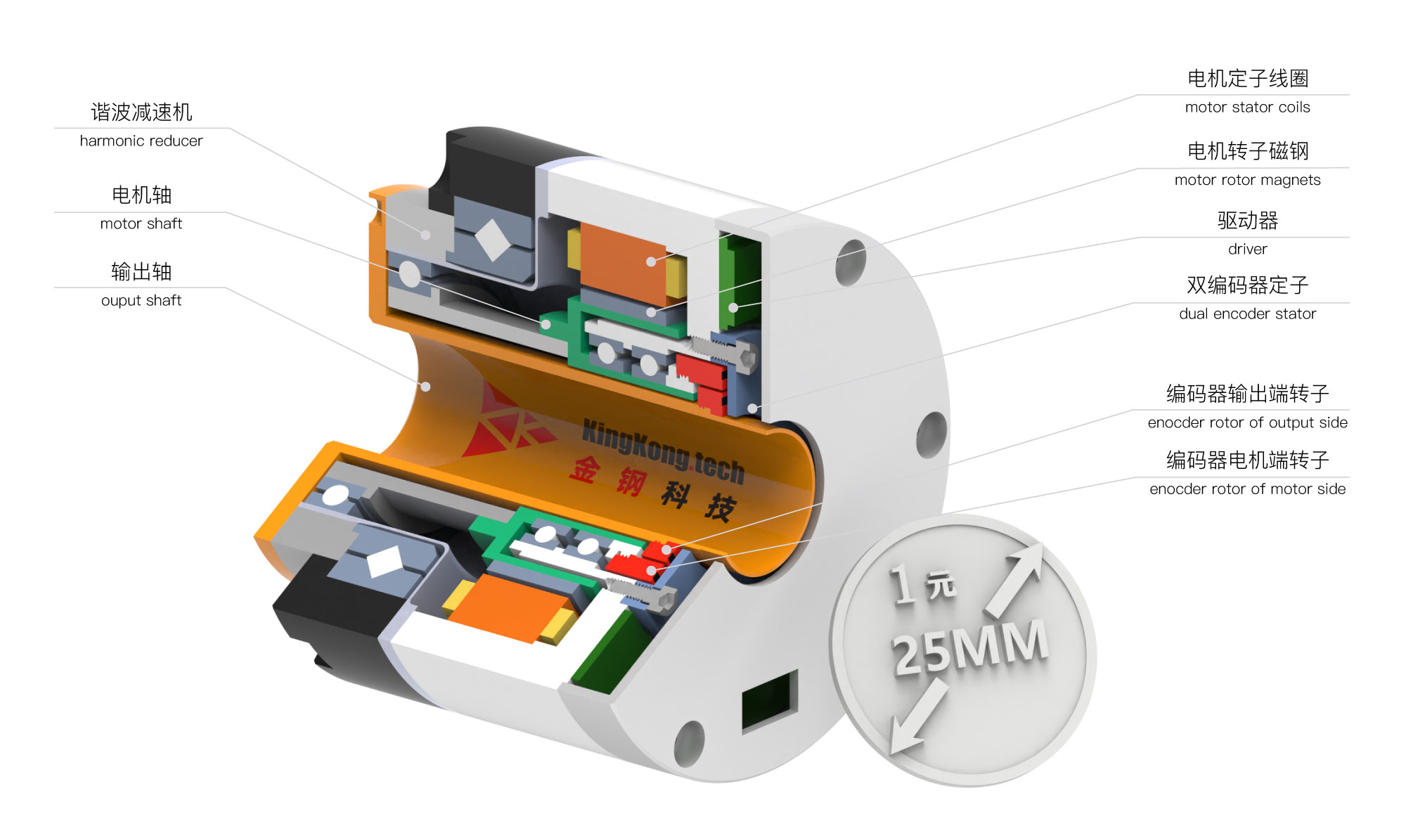
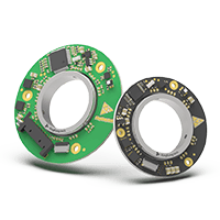
The DPT dual encoder model used in this case isDPT-15-20-30, The parameters in the model number represent:
- 15: The inner side of the inner rotor features an M15×0.4 mm thread.
- 20: The inner side of the outer rotor features an M20×0.4 mm thread.
- 30: The stator outer diameter is 30 mm.
Achieving dual 24-bit absolute outputs in such a compact size, with a large 13mm hollow bore, this encoder fits into a space comparable to a coin. Its tight design enables superior control of the joint’s measurement accuracy and resolution.From a global perspective, only Kingkong Technology is capable of delivering such an exceptional product.
Mounting
When installing the dual encoder product, all three components use tolerance fits to ensure high-precision assembly:
- Outer rotor: Threaded to secure onto the motor shaft, the inner tolerance fit between the mating surfaces and the shaft ensures high concentricity.
- Inner rotor: Threaded to lock onto the output shaft, the inner tolerance fit between the mating surfaces and the shaft ensures high concentricity
- Dual encoder stator: The stator outer diameter is tolerance-fitted to the housing to achieve high concentricity
Based on the tolerance fits of these three components, the encoder can operate with high precision.
Recalibration process
KingKong Technology’s patterned magnetic encoders are calibrated and aligned before leaving the factory. However, after installation in the final product, various mounting misalignments may affect measurement accuracy. To address this, KingKong Technology provides a recalibration process to help customers easily achieve optimal measurement precision in actual use.
During recalibration, the customer rotates the motor manually or via sensorless drive. The encoder collects data through a full rotation, and Kingkong Technology’s unique spatial calibration algorithm detects installation errors, including:
- Radial error
- Axial error
- Tilt error
KingKong Technology’s unique spatial error identification technology It precisely measures spatial errors, compensates angle deviations, and updates the encoder to ensure high accuracy despite structural errors.
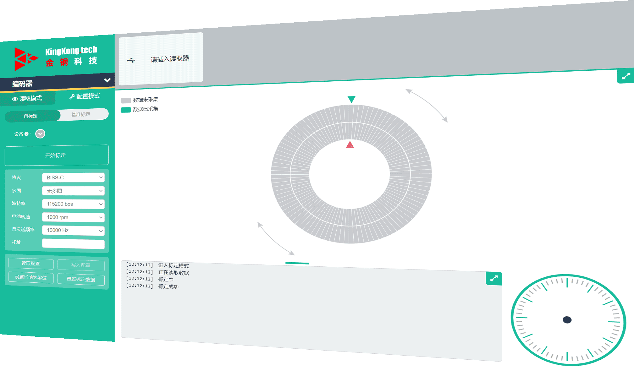
Below is the interface of KingKong Technology’s recalibration software:
In the future
While Kingkong Technology has made the dual encoder nearly invisible within the joint, we will offer customers more foundational physical measurements in the next version.Using dual encoders to sense structural stiffness, we further help customers achieve high-precision measurement of joint torque.
When customers need torque measurements, there’s no need to add a separate torque sensor,With a single command, customers can read the joint’s high-precision torque value, helping reduce joint size and enhance environmental sensing capabilities.