
2026-08-24
From “Install with Care” to “Take the Beating”: Inside the High Tolerance of KingKong Encoders
From Static Installation to Dynamic Tolerance: Rethinking Encoder Reliability in Robot Joints

Inside a robot joint, the encoder carries the critical task of angle feedback. It works like the joint's eyes, continuously and stably reporting joint position back to the control system. The moment its angle output goes wrong, the controller may act on unreliable position data and over-correct, leading to joint judder, alarms or unplanned stops. For a robot joint, an encoder must not only see accurately — it must keep seeing accurately under sustained motion and complex loads.
Why Does a Joint Test Fine on the Bench but Misbehave on the Robot?
A joint runs perfectly on the test bench, then misbehaves once it is installed in the full robot. Many robot joint engineers have run into this. What makes it worse: after the engineer painstakingly removes the joint and puts it back on the bench, the fault often disappears. Without a reproducible failure, troubleshooting loses its footing.
So why doesn't bench testing catch it?
In typical industrial equipment, a motor follows a predefined trajectory. Its speed, load direction, duty cycle and mounting conditions are relatively well defined, so engineers can size and design the structure around known operating conditions. Even with acceleration, deceleration and varying loads, the operating envelope is usually predictable and repeatable, and a test bench models it well. A robot joint is different: the conditions it faces are far more complex and variable.
A robot is a multi-joint coupled system. Every joint both drives the machine and is driven in return by the motion of other joints, by changes in posture, by load transfer and by contact with the outside world. The load a joint carries at one instant can change in magnitude — or even direction — in the next movement. The same motion can produce completely different load states depending on posture, payload and landing conditions.
And this variability is becoming more pronounced.
Recent robot games and public demonstrations make it plain to see: robot motion capability is advancing fast. What used to be relatively slow, cautious walking is now running, jumping, rapid turning, repeated take-offs and landings, and locomotion over complex terrain. The faster and larger a robot's movements, the more complex the instantaneous loads and bending moments on its joints — and the more the relative changes inside the structure under load deserve attention.
However Precise the Static Build, One Dynamic Jolt Undoes It
In a robot joint the encoder acts as the eyes. Once the eyes go wrong, the whole motor judders, raises alarms, shuts down — one problem after another.
Encoders normally ship with a list of installation requirements: air gap, eccentricity, parallelism, and so on.
Those parameters mainly define the assembly accuracy expected the moment the encoder has just been fitted. KingKong calls these the static installation parameters, and a sound static assembly is the foundation of high-precision measurement.
But however well it is assembled statically, every key parameter has to be reconsidered once the robot starts moving. A rotor and stator that met the static requirements will shift axially and radially under load, and take on structural deformation from various bending moments. When the load disappears, those changes are hard to measure after the fact. We define the structural change caused under load as dynamic variation — and once it exceeds the encoder's tolerance boundary, the angle output can go wrong.
Put simply: static parameters decide whether it starts out accurate; dynamic tolerance decides whether it stays accurate at speed. Many encoders on the market only specify the customer's static installation figures and say very little about their own dynamic tolerance, so awareness of this dimension is generally weak.
We Flipped the Logic: Let the Encoder Adapt to the Joint, Not the Other Way Round
The industry's mainstream approach has been for the encoder to impose demanding installation requirements, and for the customer to spend on tighter machining tolerances, higher-grade bearings and extra assembly inspection steps. Costs went up, yield came down, and the problem was still not solved at the root. We do it the other way round. First we study the installation deviations and dynamic variations that are unavoidable in a real joint, then we make the encoder itself cover those boundaries. In plain terms, we turned “the customer adapts to the encoder” into “the encoder adapts to the real joint”. This is not a lowering of standards — it means the encoder shoulders more system-level responsibility, shifting from selling a component to solving a class of problems for the customer. Today we can already tolerate multiple coupled dynamic conditions — axial, radial, rotor tilt, stator tilt — and keep the encoder stable across those combined cases.
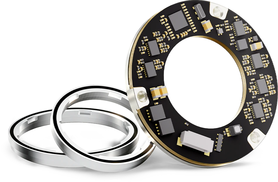
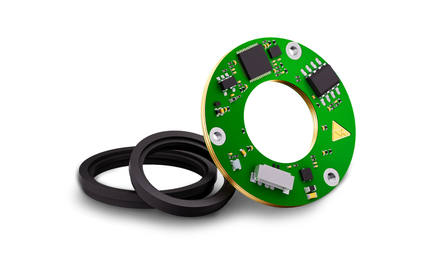
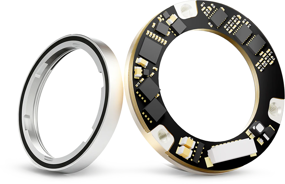
Take the DPT Series: A Look at How It Evolved
How Did We Do It? By Taming Magnetic Field Distortion
When a joint moves and takes load, the relative position of encoder rotor and stator changes and the magnetic field information departs from its ideal state. If the system cannot correctly identify and handle that, the angle output can go wrong. The core thing we built is the ability to recognise magnetic field distortion and reject its interference: however much it shakes, however far it shifts, the system identifies the distortion itself and corrects in real time. Today the KingKong DPT series holds roughly 80% share of the robot joint magnetic encoder market — that is, 8 out of every 10 robots on the market run our solution. The series has been validated across a large body of real operating conditions, and its dynamic tolerance has been iterated far beyond the boundaries originally defined, as the table above makes clear. An 80% share is simply what most users have chosen.
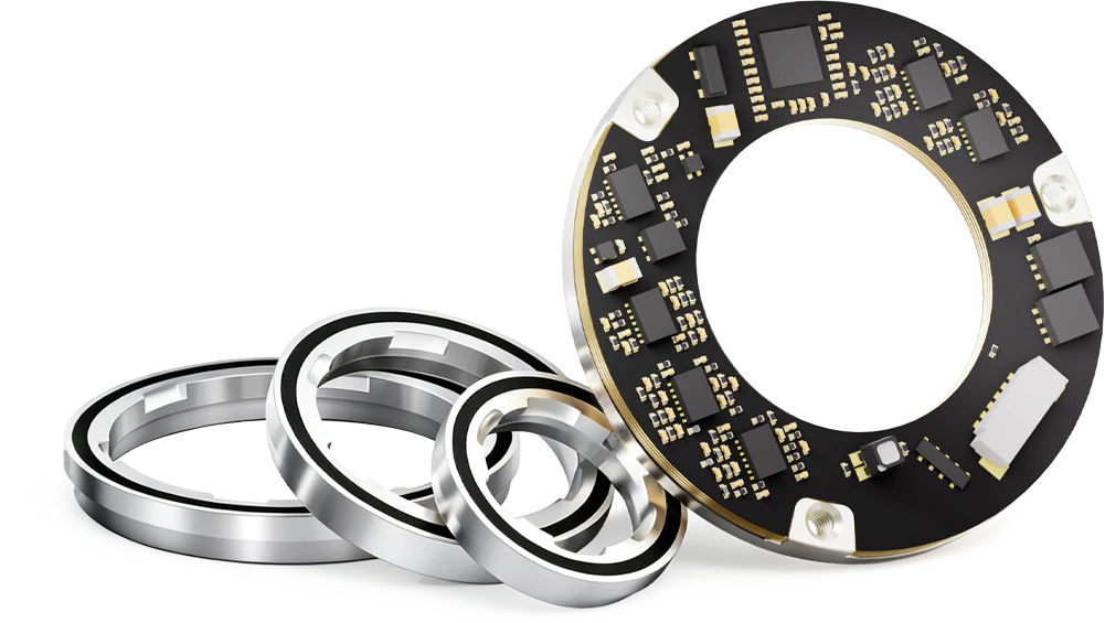
Harder Running, Jumping and Impact? The DPB Dual-Encoder Solution
If the DPT is the all-rounder, then for high-frequency impact scenarios such as robot dogs and legged robots we also offer the DPB dual-encoder solution. The series widens the structural design and dynamic operating envelope further: the static installation air gap has been opened up to 0.8±0.3mm, and dynamic stability is still guaranteed across the over-range band. We will cover the structural characteristics and dynamic tolerance of the DPB series in more detail in a future article — in the meantime you are welcome to head to our website for an early look: kingkong.tech/en/encoder/DPB
One Last Straight Word
We have always put stability in real applications first, and we will keep meeting what the robotics market actually needs by widening the usable envelope of our encoders under non-ideal structures and dynamic conditions. Robots are changing; we change faster. Our goal has never been to produce a good-looking datasheet — it is to make encoders genuinely usable inside real joints: tolerant of change, and steady under it.